
- school Campus Bookshelves
- menu_book Bookshelves
- perm_media Learning Objects
- login Login
- how_to_reg Request Instructor Account
- hub Instructor Commons

Margin Size
- Download Page (PDF)
- Download Full Book (PDF)
- Periodic Table
- Physics Constants
- Scientific Calculator
- Reference & Cite
- Tools expand_more
- Readability
selected template will load here
This action is not available.

23.3: RLC Series AC Circuits
- Last updated
- Save as PDF
- Page ID 2718

\( \newcommand{\vecs}[1]{\overset { \scriptstyle \rightharpoonup} {\mathbf{#1}} } \)
\( \newcommand{\vecd}[1]{\overset{-\!-\!\rightharpoonup}{\vphantom{a}\smash {#1}}} \)
\( \newcommand{\id}{\mathrm{id}}\) \( \newcommand{\Span}{\mathrm{span}}\)
( \newcommand{\kernel}{\mathrm{null}\,}\) \( \newcommand{\range}{\mathrm{range}\,}\)
\( \newcommand{\RealPart}{\mathrm{Re}}\) \( \newcommand{\ImaginaryPart}{\mathrm{Im}}\)
\( \newcommand{\Argument}{\mathrm{Arg}}\) \( \newcommand{\norm}[1]{\| #1 \|}\)
\( \newcommand{\inner}[2]{\langle #1, #2 \rangle}\)
\( \newcommand{\Span}{\mathrm{span}}\)
\( \newcommand{\id}{\mathrm{id}}\)
\( \newcommand{\kernel}{\mathrm{null}\,}\)
\( \newcommand{\range}{\mathrm{range}\,}\)
\( \newcommand{\RealPart}{\mathrm{Re}}\)
\( \newcommand{\ImaginaryPart}{\mathrm{Im}}\)
\( \newcommand{\Argument}{\mathrm{Arg}}\)
\( \newcommand{\norm}[1]{\| #1 \|}\)
\( \newcommand{\Span}{\mathrm{span}}\) \( \newcommand{\AA}{\unicode[.8,0]{x212B}}\)
\( \newcommand{\vectorA}[1]{\vec{#1}} % arrow\)
\( \newcommand{\vectorAt}[1]{\vec{\text{#1}}} % arrow\)
\( \newcommand{\vectorB}[1]{\overset { \scriptstyle \rightharpoonup} {\mathbf{#1}} } \)
\( \newcommand{\vectorC}[1]{\textbf{#1}} \)
\( \newcommand{\vectorD}[1]{\overrightarrow{#1}} \)
\( \newcommand{\vectorDt}[1]{\overrightarrow{\text{#1}}} \)
\( \newcommand{\vectE}[1]{\overset{-\!-\!\rightharpoonup}{\vphantom{a}\smash{\mathbf {#1}}}} \)
Learning Objectives
By the end of this section, you will be able to:
- Calculate the impedance, phase angle, resonant frequency, power, power factor, voltage, and/or current in a RLC series circuit.
- Draw the circuit diagram for an RLC series circuit.
- Explain the significance of the resonant frequency.
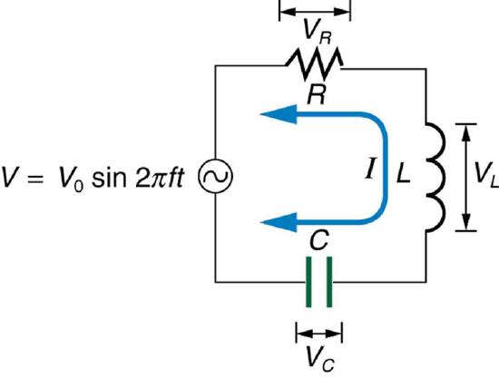
When alone in an AC circuit, inductors, capacitors, and resistors all impede current. How do they behave when all three occur together? Interestingly, their individual resistances in ohms do not simply add. Because inductors and capacitors behave in opposite ways, they partially to totally cancel each other’s effect. Figure shows an RLC series circuit with an AC voltage source, the behavior of which is the subject of this section. The crux of the analysis of an RLC circuit is the frequency dependence of \(X_L\) and \(X_C\), and the effect they have on the phase of voltage versus current (established in the preceding section). These give rise to the frequency dependence of the circuit, with important “resonance” features that are the basis of many applications, such as radio tuners.
The combined effect of resistance \(R\), inductive reactance \(X_L\), and capacitive reactance \(X_C\) is defined to be impedance , an AC analogue to resistance in a DC circuit. Current, voltage, and impedance in an RLC circuit are related by an AC version of Ohm’s law:
\[I_0 = \dfrac{V_0}{Z} \, or \, I_{rms} = \dfrac{V_{rms}}{Z}.\]
Here \(I_0\) is the peak current, \(V_0\) the peak source voltage, and \(Z\) is the impedance of the circuit. The units of impedance are ohms, and its effect on the circuit is as you might expect: the greater the impedance, the smaller the current. To get an expression for \(Z\) in terms of \(R\), \(X_L\), and \(X_C\), we will now examine how the voltages across the various components are related to the source voltage. Those voltages are labeled \(V_R\), \(V_L\) and \(V_C\) in Figure .
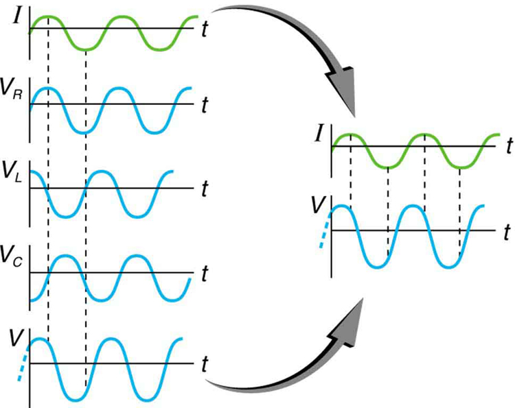
Conservation of charge requires current to be the same in each part of the circuit at all times, so that we can say the currents in \(R\), \(L\), and \(C\) are equal and in phase. But we know from the preceding section that the voltage across the inductor \(V_L\) leads the current by one-fourth of a cycle, the voltage across the capacitor \(V_C\) follows the current by one-fourth of a cycle, and the voltage across the resistor \(V_R\) is exactly in phase with the current. Figure shows these relationships in one graph, as well as showing the total voltage around the circuit \(V = V_R + V_L + V_C\), where all four voltages are the instantaneous values. According to Kirchhoff’s loop rule, the total voltage around the circuit \(V\) is also the voltage of the source.
You can see from Figure that while \(V_R\) is in phase with the current, \(V_L\) leads by \(90^o\), and \(V_C\) follows by \(90^o\). Thus \(V_L\) and \(V_C\) are \(180^o\) out of phase (crest to trough) and tend to cancel, although not completely unless they have the same magnitude. Since the peak voltages are not aligned (not in phase), the peak voltage \(V_0\) of the source does not equal the sum of the peak voltages across \(R\), \(L\), and \(C\). The actual relationship is
\[V_0 = \sqrt{V_{0R}^2 + (V_{0L} - V_{0C})^2},\] where \(V_{0R}\), \(V_{0L}\), and \(V_{0C}\) are the peak voltages across \(R\), \(L\), and \(C\), respectively. Now, using Ohm’s law and definitions from Reactance, Inductive and Capacitive , we substitute \(V_0 = I_0Z\) into the above, as well as \(V_{0R} = I_0R\), \(V_{0L} = I_0X_L\), and \(V_{0C} = I_0X_C\), yielding
\[I_0Z = \sqrt{I_0^2R^2 + (I_0X_L - I_0X_C)^2} = I_0\sqrt{R^2 + (X_L - X_C)^2}.\]
\(I_0\) cancels to yield an expression for \(Z\):
\[Z = \sqrt{R^2 + (X_L - X_C)^2},\] which is the impedance of an RLC series AC circuit. For circuits without a resistor, take \(R = 0\); for those without an inductor, take \(X_L = 0\); and for those without a capacitor, take \(X_C = 0\).
Example \(\PageIndex{1}\) : Calculating Impedance and Current
An RLC series circuit has a \(40.0 \, \Omega\) resistor, a 3.00 mH inductor, and a \(5.00 \, \mu F\) capacitor. (a) Find the circuit’s impedance at 60.0 Hz and 10.0 kHz, noting that these frequencies and the values for \(L\) and \(C\) are the same as in [link] and [link] . (b) If the voltage source has \(V_{rms} = 120 \, V\), what is \(I_{rms}\) at each frequency?
For each frequency, we use \(Z = \sqrt{R^2 + (X_L - X_C)^2}\) to find the impedance and then Ohm’s law to find current. We can take advantage of the results of the previous two examples rather than calculate the reactances again.
Solution for (a)
At 60.0 Hz, the values of the reactances were found in [link] to be \(X_L = 1.13 \, \Omega\) and in [link] to be \(X_C = 531 \, \Omega\). Entering these and the given \(40.0 \, \Omega\) for resistance into \(Z = \sqrt{R^2 +(X_L - X_C)^2}\) yields
\[Z = \sqrt{R^2 +(X_L - X_C)^2}\]
\[= \sqrt{(40.0 \, )^2 + (1.13 \, \Omega - 531 \, \Omega)^2}\]
\[= 531 \, \Omega \, at \, 60.0 \, Hz.\]
Similarly, at 10.0 kHz, \(X_L = 188 \, \Omega\) and \(X_C = 3.18 \, \Omega\), so that
\[Z = \sqrt{(40.0 \, \Omega)^2 + (188 \, \Omega - 3.18 \, \Omega)^2}\]
\[= 190 \, \Omega \, at \, 10.0 \, kHz.\]
Discussion for (a)
In both cases, the result is nearly the same as the largest value, and the impedance is definitely not the sum of the individual values. It is clear that \(X_L\) dominates at high frequency and \(X_C\) dominates at low frequency.
Solution for (b)
The current \(I_{rms}\) can be found using the AC version of Ohm’s law in Equation \(I_{rms} = V_{rms}/Z\).
\[I_{rms} = \dfrac{V_{rms}}{Z} = \dfrac{120 \, V}{531 \, \Omega} = 0.226 \, A \, at \, 60.0 \, Hz.\]
Finally, at 10.0 kHz we find
\[I_{rms} = \dfrac{V_{rms}}{Z} = \dfrac{120 \, V}{180 \, \Omega} = 0.633 \, A \, at \, 10.0 \, Hz.\]
The current at 60.0 Hz is the same (to three digits) as found for the capacitor alone in [link] . The capacitor dominates at low frequency. The current at 10.0 kHz is only slightly different from that found for the inductor alone in [link] . The inductor dominates at high frequency.
Resonance in RLC Series AC Circuits
How does an RLC circuit behave as a function of the frequency of the driving voltage source? Combining Ohm’s law, \(I_{rms} = V_{rms}/Z\), and the expression for impedance \(Z\) from \(Z = \sqrt{R^2 + (X_L - X_C)^2}\) gives
\[I_{rms} = \dfrac{V_{rms}}{\sqrt{R^2 + (X_L = X_C)^2}}.\]
The reactances vary with frequency, with \(X_L\) large at high frequencies and \(X_C\) large at low frequencies, as we have seen in three previous examples. At some intermediate frequency \(f_0\), the reactances will be equal and cancel, giving \(Z = R\) —this is a minimum value for impedance, and a maximum value for \(I_{rms}\) results. We can get an expression for \(f_0\) by taking
\[X_L = X_C.\]
Substituting the definitions of \(X_L\) and \(X_C\),
\[2\pi f_0 L = \dfrac{1}{2\pi f_0 C}.\]
Solving this expression for \(f_0\) yields
\[f_0 = \dfrac{1}{2\pi \sqrt{LC}},\] where \(F_0\) is the resonant frequency of an RLC series circuit. This is also the natural frequency at which the circuit would oscillate if not driven by the voltage source. At \(f_0\), the effects of the inductor and capacitor cancel, so that \(Z = R\), and \(I_{rms}\) is a maximum.
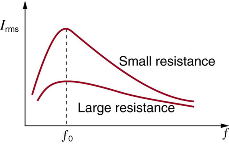
Resonance in AC circuits is analogous to mechanical resonance, where resonance is defined to be a forced oscillation—in this case, forced by the voltage source—at the natural frequency of the system. The receiver in a radio is an RLC circuit that oscillates best at its \(f_0\). A variable capacitor is often used to adjust \(f_0\) to receive a desired frequency and to reject others. Figure is a graph of current as a function of frequency, illustrating a resonant peak in \(I_{rms}\) at \(f_0\). The two curves are for two different circuits, which differ only in the amount of resistance in them. The peak is lower and broader for the higher-resistance circuit. Thus the higher-resistance circuit does not resonate as strongly and would not be as selective in a radio receiver, for example.
Example \(\PageIndex{2}\): Calculating Resonant Frequency and Current
For the same RLC series circuit having a \(40.0 \, \Omega\) resistor, a 3.00 mH inductor, and a \(5.00 \, \mu F\) capacitor: (a) Find the resonant frequency. (b) Calculate \(I_{rms}\) at resonance if \(V_{rms}\) is 120 V.
The resonant frequency is found by using the expression in \(f_0 = \frac{1}{2\pi \sqrt{LC}}\).
The current at that frequency is the same as if the resistor alone were in the circuit.
Entering the given values for \(L\) and \(C\) into the expression given for \(f_0\) in \(f_0 = \frac{1}{2\pi \sqrt{LC}}\) yields
\[f_0 = \dfrac{1}{2\pi \sqrt{LC}}\]
\[= \dfrac{1}{2 \pi \sqrt{(3.00 \times 10^{-3} \, H)(5.00 \times 10^{-6} \, F)}} = 1.30 \, kHz.\]
We see that the resonant frequency is between 60.0 Hz and 10.0 kHz, the two frequencies chosen in earlier examples. This was to be expected, since the capacitor dominated at the low frequency and the inductor dominated at the high frequency. Their effects are the same at this intermediate frequency.
The current is given by Ohm’s law. At resonance, the two reactances are equal and cancel, so that the impedance equals the resistance alone. Thus,
\[I_{rms} = \dfrac{V_{rms}}{Z} = \dfrac{120 \, V}{40.0 \, \Omega} = 3.00 \, A.\]
Discussion for (b)
At resonance, the current is greater than at the higher and lower frequencies considered for the same circuit in the preceding example.
Power in RLC Series AC Circuits
If current varies with frequency in an RLC circuit, then the power delivered to it also varies with frequency. But the average power is not simply current times voltage, as it is in purely resistive circuits. As was seen in Figure , voltage and current are out of phase in an RLC circuit. There is a phase angle \(\phi\) between the source voltage \(V\) and the current \(I\), which can be found from
\[cos \, \phi = \dfrac{R}{Z}.\]
For example, at the resonant frequency or in a purely resistive circuit \(Z = R\), so that \(cos \, \phi = 1\). This implies that \(\phi = 0^o\) and that voltage and current are in phase, as expected for resistors. At other frequencies, average power is less than at resonance. This is both because voltage and current are out of phase and because \(I_{rms}\) is lower. The fact that source voltage and current are out of phase affects the power delivered to the circuit. It can be shown that the average power is
\[P_{ave} = I_{rms}V_{rms}cos \, \phi,\] thus \(cos \, \phi\) is called the power factor , which can range from 0 to 1. Power factors near 1 are desirable when designing an efficient motor, for example. At the resonant frequency, \(cos \, \phi = 1\).
Example \(\PageIndex{3}\) : Calculating the Power Factor and Power
For the same RLC series circuit having a \(40.0 \, \Omega\) resistor, a 3.00 mH inductor, a \(5.00 \, \mu F\) capacitor, and a voltage source with a \(V_{rms}\) of 120 V: (a) Calculate the power factor and phase angle for \(f = 60.0 \, Hz.\)
(b) What is the average power at 50.0 Hz? (c) Find the average power at the circuit’s resonant frequency.
Strategy and Solution for (a)
The power factor at 60.0 Hz is found from
We know \(Z = 531 \, \Omega \) from Example , so that
\[cos \, \phi = \dfrac{40.0 \, \Omega}{531 \, \Omega} = 0.0753 \, at \, 60.0 \, Hz.\]
This small value indicates the voltage and current are significantly out of phase. In fact, the phase angle is
\[\phi = cos^{-1} \, 0.0753 = 85.7^o \, at \, 60.0 \, Hz.\]
The phase angle is close to \(90^o\), consistent with the fact that the capacitor dominates the circuit at this low frequency (a pure RC circuit has its voltage and current \(90^o\) out of phase).
Strategy and Solution for (b)
The average power at 60.0 Hz is
\[P_{ave} = I_{rms}V_{rms}cos \, \phi.\]
\(I_{rms}\) was found to be 0.226 A in Example . Entering the known values gives
\[P_{ave} = (0.226 \, A)(120 \, V)(0.0753) = 2.04 \, W \, at \, 60.0 \, Hz.\]
Strategy and Solution for (c)
At the resonant frequency, we know \(cos \, \phi = 1\), and \(I_{rms}\) was found to be 6.00 A in Example . Thus,
\[P_{ave} = (3.00 \, A)(120 \, V)(1) = 360 \, W\)
at resonance (1.30 kHz)
Both the current and the power factor are greater at resonance, producing significantly greater power than at higher and lower frequencies.
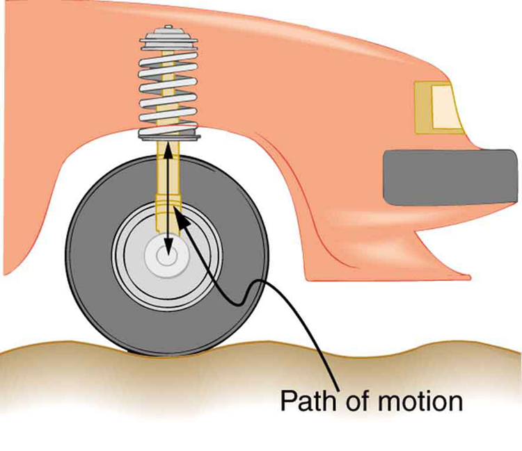
Power delivered to an RLC series AC circuit is dissipated by the resistance alone. The inductor and capacitor have energy input and output but do not dissipate it out of the circuit. Rather they transfer energy back and forth to one another, with the resistor dissipating exactly what the voltage source puts into the circuit. This assumes no significant electromagnetic radiation from the inductor and capacitor, such as radio waves. Such radiation can happen and may even be desired, as we will see in the next chapter on electromagnetic radiation, but it can also be suppressed as is the case in this chapter. The circuit is analogous to the wheel of a car driven over a corrugated road as shown in Figure . The regularly spaced bumps in the road are analogous to the voltage source, driving the wheel up and down. The shock absorber is analogous to the resistance damping and limiting the amplitude of the oscillation. Energy within the system goes back and forth between kinetic (analogous to maximum current, and energy stored in an inductor) and potential energy stored in the car spring (analogous to no current, and energy stored in the electric field of a capacitor). The amplitude of the wheels’ motion is a maximum if the bumps in the road are hit at the resonant frequency.
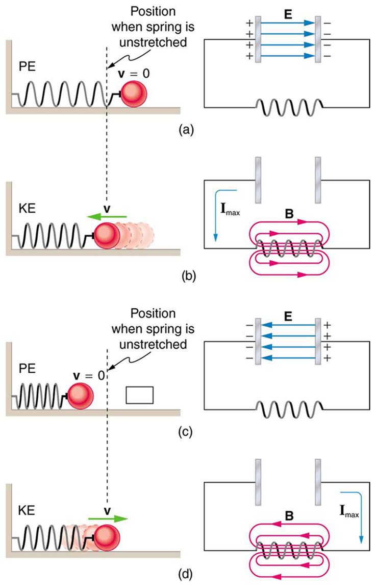
A pure LC circuit with negligible resistance oscillates at \(f_0\), the same resonant frequency as an RLC circuit. It can serve as a frequency standard or clock circuit—for example, in a digital wristwatch. With a very small resistance, only a very small energy input is necessary to maintain the oscillations. The circuit is analogous to a car with no shock absorbers. Once it starts oscillating, it continues at its natural frequency for some time. Figure shows the analogy between an LC circuit and a mass on a spring.
PHET EXPLORATIONS: CIRCUIT CONSTRUCTION KIT (AC + DC), VIRTUAL LAB
Build circuits with capacitors, inductors, resistors and AC or DC voltage sources, and inspect them using lab instruments such as voltmeters and ammeters.
- The AC analogy to resistance is impedance \(Z\), the combined effect of resistors, inductors, and capacitors, defined by the AC version of Ohm’s law: \[I_0 = \dfrac{V_0}{Z} \, or \, I_{rms} = \dfrac{V_{rms}}{Z},\] where \(I_0\) is the peak current and \(V_0\) is the peak source voltage.
- Impedance has units of ohms and is given by \(Z = \sqrt{R^2 + (X_L - X_C)^2}\).
- The resonant frequency \(f_0\), at which \(X_L = X_C\), is \[f_0 = \dfrac{1}{2\pi \sqrt{LC}}.\]
- In an AC circuit, there is a phase angle \(\phi\) between source voltage \(V\) and the current \(I\) which can be found from \[cos \, \phi = \dfrac{R}{Z},\]
- \(\phi = 0^o\) for a purely resistive circuit or an RLC circuit at resonance.
- The average power delivered to an RLC circuit is affected by the phase angle and is given by \[P_{ave} = I_{rms}V_{rms} \, cos \, \phi,\] \(cos \, \phi\) is called the power factor, which ranges from 0 to 1.
23.12 RLC Series AC Circuits
Learning objectives.
By the end of this section, you will be able to:
- Calculate the impedance, phase angle, resonant frequency, power, power factor, voltage, and/or current in a RLC series circuit.
- Draw the circuit diagram for an RLC series circuit.
- Explain the significance of the resonant frequency.
When alone in an AC circuit, inductors, capacitors, and resistors all impede current. How do they behave when all three occur together? Interestingly, their individual resistances in ohms do not simply add. Because inductors and capacitors behave in opposite ways, they partially to totally cancel each other’s effect. Figure 23.46 shows an RLC series circuit with an AC voltage source, the behavior of which is the subject of this section. The crux of the analysis of an RLC circuit is the frequency dependence of X L X L and X C X C , and the effect they have on the phase of voltage versus current (established in the preceding section). These give rise to the frequency dependence of the circuit, with important “resonance” features that are the basis of many applications, such as radio tuners.
The combined effect of resistance R R , inductive reactance X L X L , and capacitive reactance X C X C is defined to be impedance , an AC analogue to resistance in a DC circuit. Current, voltage, and impedance in an RLC circuit are related by an AC version of Ohm’s law:
Here I 0 I 0 is the peak current, V 0 V 0 the peak source voltage, and Z Z is the impedance of the circuit. The units of impedance are ohms, and its effect on the circuit is as you might expect: the greater the impedance, the smaller the current. To get an expression for Z Z in terms of R R , X L X L , and X C X C , we will now examine how the voltages across the various components are related to the source voltage. Those voltages are labeled V R V R , V L V L , and V C V C in Figure 23.46 .
Conservation of charge requires current to be the same in each part of the circuit at all times, so that we can say the currents in R R , L L , and C C are equal and in phase. But we know from the preceding section that the voltage across the inductor V L V L leads the current by one-fourth of a cycle, the voltage across the capacitor V C V C follows the current by one-fourth of a cycle, and the voltage across the resistor V R V R is exactly in phase with the current. Figure 23.47 shows these relationships in one graph, as well as showing the total voltage around the circuit V = V R + V L + V C V = V R + V L + V C , where all four voltages are the instantaneous values. According to Kirchhoff’s loop rule, the total voltage around the circuit V V is also the voltage of the source.
You can see from Figure 23.47 that while V R V R is in phase with the current, V L V L leads by 90º 90º , and V C V C follows by 90º 90º . Thus V L V L and V C V C are 180º 180º out of phase (crest to trough) and tend to cancel, although not completely unless they have the same magnitude. Since the peak voltages are not aligned (not in phase), the peak voltage V 0 V 0 of the source does not equal the sum of the peak voltages across R R , L L , and C C . The actual relationship is
where V 0 R V 0 R , V 0 L V 0 L , and V 0 C V 0 C are the peak voltages across R R , L L , and C C , respectively. Now, using Ohm’s law and definitions from Reactance, Inductive and Capacitive , we substitute V 0 = I 0 Z V 0 = I 0 Z into the above, as well as V 0 R = I 0 R V 0 R = I 0 R , V 0 L = I 0 X L V 0 L = I 0 X L , and V 0 C = I 0 X C V 0 C = I 0 X C , yielding
I 0 I 0 cancels to yield an expression for Z Z :
which is the impedance of an RLC series AC circuit. For circuits without a resistor, take R = 0 R = 0 ; for those without an inductor, take X L = 0 X L = 0 ; and for those without a capacitor, take X C = 0 X C = 0 .
Example 23.12
Calculating impedance and current.
An RLC series circuit has a 40.0 Ω 40.0 Ω resistor, a 3.00 mH inductor, and a 5.00 μF 5.00 μF capacitor. (a) Find the circuit’s impedance at 60.0 Hz and 10.0 kHz, noting that these frequencies and the values for L L and C C are the same as in Example 23.10 and Example 23.11 . (b) If the voltage source has V rms = 120 V V rms = 120 V , what is I rms I rms at each frequency?
For each frequency, we use Z = R 2 + ( X L − X C ) 2 Z = R 2 + ( X L − X C ) 2 to find the impedance and then Ohm’s law to find current. We can take advantage of the results of the previous two examples rather than calculate the reactances again.
Solution for (a)
At 60.0 Hz, the values of the reactances were found in Example 23.10 to be X L = 1 . 13 Ω X L = 1 . 13 Ω and in Example 23.11 to be X C = 531 Ω X C = 531 Ω . Entering these and the given 40.0 Ω 40.0 Ω for resistance into Z = R 2 + ( X L − X C ) 2 Z = R 2 + ( X L − X C ) 2 yields
Similarly, at 10.0 kHz, X L = 188 Ω X L = 188 Ω and X C = 3 . 18 Ω X C = 3 . 18 Ω , so that
Discussion for (a)
In both cases, the result is nearly the same as the largest value, and the impedance is definitely not the sum of the individual values. It is clear that X L X L dominates at high frequency and X C X C dominates at low frequency.
Solution for (b)
The current I rms I rms can be found using the AC version of Ohm’s law in Equation I rms = V rms / Z I rms = V rms / Z :
I rms = V rms Z = 120 V 531 Ω = 0 . 226 A I rms = V rms Z = 120 V 531 Ω = 0 . 226 A at 60.0 Hz
Finally, at 10.0 kHz, we find
I rms = V rms Z = 120 V 190 Ω = 0 . 633 A I rms = V rms Z = 120 V 190 Ω = 0 . 633 A at 10.0 kHz
The current at 60.0 Hz is the same (to three digits) as found for the capacitor alone in Example 23.11 . The capacitor dominates at low frequency. The current at 10.0 kHz is only slightly different from that found for the inductor alone in Example 23.10 . The inductor dominates at high frequency.
Resonance in RLC Series AC Circuits
How does an RLC circuit behave as a function of the frequency of the driving voltage source? Combining Ohm’s law, I rms = V rms / Z I rms = V rms / Z , and the expression for impedance Z Z from Z = R 2 + ( X L − X C ) 2 Z = R 2 + ( X L − X C ) 2 gives
The reactances vary with frequency, with X L X L large at high frequencies and X C X C large at low frequencies, as we have seen in three previous examples. At some intermediate frequency f 0 f 0 , the reactances will be equal and cancel, giving Z = R Z = R —this is a minimum value for impedance, and a maximum value for I rms I rms results. We can get an expression for f 0 f 0 by taking
Substituting the definitions of X L X L and X C X C ,
Solving this expression for f 0 f 0 yields
where f 0 f 0 is the resonant frequency of an RLC series circuit. This is also the natural frequency at which the circuit would oscillate if not driven by the voltage source. At f 0 f 0 , the effects of the inductor and capacitor cancel, so that Z = R Z = R , and I rms I rms is a maximum.
Resonance in AC circuits is analogous to mechanical resonance, where resonance is defined to be a forced oscillation—in this case, forced by the voltage source—at the natural frequency of the system. The receiver in a radio is an RLC circuit that oscillates best at its f 0 f 0 . A variable capacitor is often used to adjust f 0 f 0 to receive a desired frequency and to reject others. Figure 23.48 is a graph of current as a function of frequency, illustrating a resonant peak in I rms I rms at f 0 f 0 . The two curves are for two different circuits, which differ only in the amount of resistance in them. The peak is lower and broader for the higher-resistance circuit. Thus the higher-resistance circuit does not resonate as strongly and would not be as selective in a radio receiver, for example.
Example 23.13
Calculating resonant frequency and current.
For the same RLC series circuit having a 40.0 Ω 40.0 Ω resistor, a 3.00 mH inductor, and a 5.00 μF 5.00 μF capacitor: (a) Find the resonant frequency. (b) Calculate I rms I rms at resonance if V rms V rms is 120 V.
The resonant frequency is found by using the expression in f 0 = 1 2π LC f 0 = 1 2π LC . The current at that frequency is the same as if the resistor alone were in the circuit.
Entering the given values for L L and C C into the expression given for f 0 f 0 in f 0 = 1 2π LC f 0 = 1 2π LC yields
We see that the resonant frequency is between 60.0 Hz and 10.0 kHz, the two frequencies chosen in earlier examples. This was to be expected, since the capacitor dominated at the low frequency and the inductor dominated at the high frequency. Their effects are the same at this intermediate frequency.
The current is given by Ohm’s law. At resonance, the two reactances are equal and cancel, so that the impedance equals the resistance alone. Thus,
Discussion for (b)
At resonance, the current is greater than at the higher and lower frequencies considered for the same circuit in the preceding example.
Power in RLC Series AC Circuits
If current varies with frequency in an RLC circuit, then the power delivered to it also varies with frequency. But the average power is not simply current times voltage, as it is in purely resistive circuits. As was seen in Figure 23.47 , voltage and current are out of phase in an RLC circuit. There is a phase angle ϕ ϕ between the source voltage V V and the current I I , which can be found from
For example, at the resonant frequency or in a purely resistive circuit Z = R Z = R , so that cos ϕ = 1 cos ϕ = 1 . This implies that ϕ = 0 º ϕ = 0 º and that voltage and current are in phase, as expected for resistors. At other frequencies, average power is less than at resonance. This is both because voltage and current are out of phase and because I rms I rms is lower. The fact that source voltage and current are out of phase affects the power delivered to the circuit. It can be shown that the average power is
Thus cos ϕ cos ϕ is called the power factor , which can range from 0 to 1. Power factors near 1 are desirable when designing an efficient motor, for example. At the resonant frequency, cos ϕ = 1 cos ϕ = 1 .
Example 23.14
Calculating the power factor and power.
For the same RLC series circuit having a 40.0 Ω 40.0 Ω resistor, a 3.00 mH inductor, a 5.00 μF 5.00 μF capacitor, and a voltage source with a V rms V rms of 120 V: (a) Calculate the power factor and phase angle for f = 60 . 0 Hz f = 60 . 0 Hz . (b) What is the average power at 50.0 Hz? (c) Find the average power at the circuit’s resonant frequency.
Strategy and Solution for (a)
The power factor at 60.0 Hz is found from
We know Z = 531 Ω Z = 531 Ω from Example 23.12 , so that
This small value indicates the voltage and current are significantly out of phase. In fact, the phase angle is
The phase angle is close to 90º 90º , consistent with the fact that the capacitor dominates the circuit at this low frequency (a pure RC circuit has its voltage and current 90º 90º out of phase).
Strategy and Solution for (b)
The average power at 60.0 Hz is
I rms I rms was found to be 0.226 A in Example 23.12 . Entering the known values gives
Strategy and Solution for (c)
At the resonant frequency, we know cos ϕ = 1 cos ϕ = 1 , and I rms I rms was found to be 6.00 A in Example 23.13 . Thus,
P ave = ( 3 . 00 A ) ( 120 V ) ( 1 ) = 360 W P ave = ( 3 . 00 A ) ( 120 V ) ( 1 ) = 360 W at resonance (1.30 kHz)
Both the current and the power factor are greater at resonance, producing significantly greater power than at higher and lower frequencies.
Power delivered to an RLC series AC circuit is dissipated by the resistance alone. The inductor and capacitor have energy input and output but do not dissipate it out of the circuit. Rather they transfer energy back and forth to one another, with the resistor dissipating exactly what the voltage source puts into the circuit. This assumes no significant electromagnetic radiation from the inductor and capacitor, such as radio waves. Such radiation can happen and may even be desired, as we will see in the next chapter on electromagnetic radiation, but it can also be suppressed as is the case in this chapter. The circuit is analogous to the wheel of a car driven over a corrugated road as shown in Figure 23.49 . The regularly spaced bumps in the road are analogous to the voltage source, driving the wheel up and down. The shock absorber is analogous to the resistance damping and limiting the amplitude of the oscillation. Energy within the system goes back and forth between kinetic (analogous to maximum current, and energy stored in an inductor) and potential energy stored in the car spring (analogous to no current, and energy stored in the electric field of a capacitor). The amplitude of the wheels’ motion is a maximum if the bumps in the road are hit at the resonant frequency.
A pure LC circuit with negligible resistance oscillates at f 0 f 0 , the same resonant frequency as an RLC circuit. It can serve as a frequency standard or clock circuit—for example, in a digital wristwatch. With a very small resistance, only a very small energy input is necessary to maintain the oscillations. The circuit is analogous to a car with no shock absorbers. Once it starts oscillating, it continues at its natural frequency for some time. Figure 23.50 shows the analogy between an LC circuit and a mass on a spring.
PhET Explorations
Circuit construction kit (ac+dc), virtual lab.
Build circuits with capacitors, inductors, resistors and AC or DC voltage sources, and inspect them using lab instruments such as voltmeters and ammeters.
As an Amazon Associate we earn from qualifying purchases.
This book may not be used in the training of large language models or otherwise be ingested into large language models or generative AI offerings without OpenStax's permission.
Want to cite, share, or modify this book? This book uses the Creative Commons Attribution License and you must attribute OpenStax.
Access for free at https://openstax.org/books/college-physics-2e/pages/1-introduction-to-science-and-the-realm-of-physics-physical-quantities-and-units
- Authors: Paul Peter Urone, Roger Hinrichs
- Publisher/website: OpenStax
- Book title: College Physics 2e
- Publication date: Jul 13, 2022
- Location: Houston, Texas
- Book URL: https://openstax.org/books/college-physics-2e/pages/1-introduction-to-science-and-the-realm-of-physics-physical-quantities-and-units
- Section URL: https://openstax.org/books/college-physics-2e/pages/23-12-rlc-series-ac-circuits
© Jan 19, 2024 OpenStax. Textbook content produced by OpenStax is licensed under a Creative Commons Attribution License . The OpenStax name, OpenStax logo, OpenStax book covers, OpenStax CNX name, and OpenStax CNX logo are not subject to the Creative Commons license and may not be reproduced without the prior and express written consent of Rice University.

- school Campus Bookshelves
- menu_book Bookshelves
- perm_media Learning Objects
- login Login
- how_to_reg Request Instructor Account
- hub Instructor Commons

Margin Size
- Download Page (PDF)
- Download Full Book (PDF)
- Periodic Table
- Physics Constants
- Scientific Calculator
- Reference & Cite
- Tools expand_more
- Readability
selected template will load here
This action is not available.

8.2: Series Resonance
- Last updated
- Save as PDF
- Page ID 25287

- James M. Fiore
- Mohawk Valley Community College
\( \newcommand{\vecs}[1]{\overset { \scriptstyle \rightharpoonup} {\mathbf{#1}} } \)
\( \newcommand{\vecd}[1]{\overset{-\!-\!\rightharpoonup}{\vphantom{a}\smash {#1}}} \)
\( \newcommand{\id}{\mathrm{id}}\) \( \newcommand{\Span}{\mathrm{span}}\)
( \newcommand{\kernel}{\mathrm{null}\,}\) \( \newcommand{\range}{\mathrm{range}\,}\)
\( \newcommand{\RealPart}{\mathrm{Re}}\) \( \newcommand{\ImaginaryPart}{\mathrm{Im}}\)
\( \newcommand{\Argument}{\mathrm{Arg}}\) \( \newcommand{\norm}[1]{\| #1 \|}\)
\( \newcommand{\inner}[2]{\langle #1, #2 \rangle}\)
\( \newcommand{\Span}{\mathrm{span}}\)
\( \newcommand{\id}{\mathrm{id}}\)
\( \newcommand{\kernel}{\mathrm{null}\,}\)
\( \newcommand{\range}{\mathrm{range}\,}\)
\( \newcommand{\RealPart}{\mathrm{Re}}\)
\( \newcommand{\ImaginaryPart}{\mathrm{Im}}\)
\( \newcommand{\Argument}{\mathrm{Arg}}\)
\( \newcommand{\norm}[1]{\| #1 \|}\)
\( \newcommand{\Span}{\mathrm{span}}\) \( \newcommand{\AA}{\unicode[.8,0]{x212B}}\)
\( \newcommand{\vectorA}[1]{\vec{#1}} % arrow\)
\( \newcommand{\vectorAt}[1]{\vec{\text{#1}}} % arrow\)
\( \newcommand{\vectorB}[1]{\overset { \scriptstyle \rightharpoonup} {\mathbf{#1}} } \)
\( \newcommand{\vectorC}[1]{\textbf{#1}} \)
\( \newcommand{\vectorD}[1]{\overrightarrow{#1}} \)
\( \newcommand{\vectorDt}[1]{\overrightarrow{\text{#1}}} \)
\( \newcommand{\vectE}[1]{\overset{-\!-\!\rightharpoonup}{\vphantom{a}\smash{\mathbf {#1}}}} \)
Let's begin with the simplest RLC circuit; one consisting of a single voltage source in series with a single resistor, inductor and capacitor, as shown in Figure \(\PageIndex{1}\). Of particular interest is how the total impedance varies across the frequency spectrum and what impact this has on the current and the three component voltages.
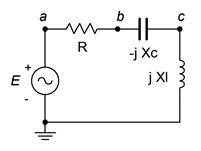
The impedance as seen by the source is simply the sum of the three components, or
\[Z = R+ jX_L − j X_C \nonumber \]
This can be expanded into
\[Z = = R+ j 2\pi f L −j \frac{1}{2\pi f C} \nonumber \]
The interesting part here is that the first term is not a function of frequency, the second term is directly proportional to frequency and the third is inversely proportional to frequency. Further, given that the positive and negative reactances behave oppositely, it appears that at some frequency they may cancel out, leaving just the resistance.
To refine this, we expect that at low frequencies the capacitor will dominate the impedance. In other words, \(X_C\) will be the largest of the three ohmic values. This means that the overall impedance will tend to mimic both the magnitude and phase of the capacitive reactance. On the other hand, at very high frequencies the inductor will tend to dominate the impedance. \(X_L\) will be the largest of the three values. In this region, the combined impedance will echo that of the inductor. In short, at low frequencies the impedance magnitude will be large and the circuit will appear capacitive while at high frequencies the impedance magnitude will be large and the circuit will appear inductive. In the middle is where things get interesting.
A plot of the resistance or reactance of the three elements is shown in Figure \(\PageIndex{2}\). The sum of the three is also shown (red). The frequency axis is uses a logarithmic scale to show the symmetrical nature of the combined impedance curve.
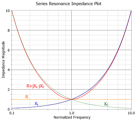
The dip in the center corresponds to an impedance equal to \(R\). At this frequency the capacitive and inductive reactances are equal in magnitude and effectively cancel each other. All that's left is the resistive component, \(R\). This frequency is known as the resonant frequency and is denoted by \(f_0\).
\[\text{The series resonant frequency, } f_0, \text{ is the frequency at which the magnitudes of the inductive and capacitive reactances are equal.} \label{8.1} \]
This implies that the power factor is unity at resonance. Also, in a real world circuit \(R\) is the combination of the series resistance plus any resistance from the inductor's coil. We can derive a formula for \(f_0\) as follows. The definition declares that the magnitude of \(X_L\) must equal the magnitude of \(X_C\). Therefore, we can set the capacitive and inductive reactance formulas equal to each other and then solve for the resulting frequency.
\[X_C = \frac{1}{2\pi f C} \\ X_L = 2\pi f L \\ X_L = X_C \\ 2\pi f_0 L = \frac{1}{2\pi f_0C} \\ f_0^2 = \frac{1}{(2\pi )^2 LC} \\ f_0 = \frac{1}{2\pi \sqrt{LC}} \label{8.2} \]
Note that a particular resonant frequency can be obtained through a variety of LC pairs. This, along with the value of \(R\), will alter the specific shape of the impedance curve in terms of how narrow or broad the dip is. These components will also affect how quickly the phase response shifts from fully capacitive (\(−90^{\circ}\)) to fully inductive (\(+90^{\circ}\)). This shape factor is described by the parameter, \(Q\). The tighter or more narrow the curve, the higher the \(Q\).
Given a constant voltage source, it should be no surprise that a plot of the resulting current will be an inversion of the impedance curve. This is shown in Figure \(\PageIndex{3}\).
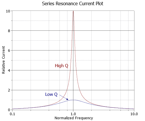
If we scale the curves such that they both have a normalized peak of unity, the difference in the shapes may be a little easier to see. This is shown in Figure \(\PageIndex{4}\).
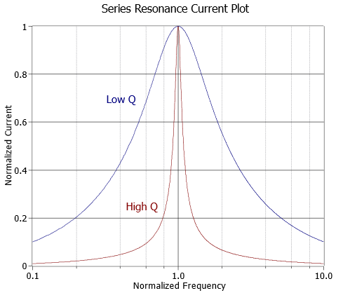
At this point we can more precisely define \(Q\). Specifically, the “sharpness” of the curve is related to the half-power or “−3 dB” frequencies, \(f_1\) and \(f_2\). 1 These are the frequencies at which the current (assuming voltage source drive) falls off to 0.707 of the maximum value at resonance. Therefore, they represent the frequencies at which power will have fallen to one-half of the maximum value seen at resonance (recall that power varies as the square of current and that 0.707 squared is approximately 0.5). \(f_1\) is below \(f_0\) and \(f_2\) is found above. The difference between these two frequencies is called the bandwidth, BW.
\[BW = f_2 − f_1 \label{8.3} \]
\[Q_{circuit} = \frac{f_0}{BW} \label{8.4} \]
The relationship between these variables is illustrated in Figure \(\PageIndex{5}\). The vertical axis is shown as a percentage of maximum. For a series resonant circuit driven by a voltage source, this axis is current; however, it can be voltage in the the case of a parallel resonant circuit, as we shall see. If this plot is compared to the curves in Figure \(\PageIndex{4}\), it should be apparent that for lower \(Q\) circuits, \(f_1\) and \(f_2\) spread apart, moving away from the resonant frequency, \(f_0\). Thus, for any given \(f_0\), a lower \(Q\) means a wider (larger) bandwidth.
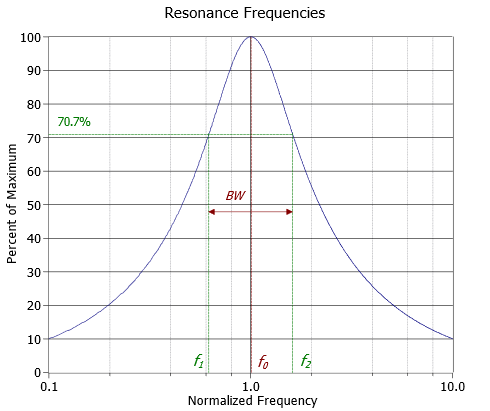
The resonant frequency, \(f_0\), in general is not located evenly between \(f_1\) and \(f_2\). It is, in fact, located at their geometric mean. In other words,
\[f_0 = \sqrt{f_1 f_2} \label{8.5} \]
From Equation \ref{8.5} we may derive:
\[\frac{f_0}{f_1} = \frac{f_2}{f_0} \label{8.6} \]
To find accurate values for \(f_1\) and \(f_2\) we can define a factor, \(k_0\). The derivation of \(k_0\) is found in Appendix C.
\[k_0 = \frac{1}{2Q_{circuit}} + \sqrt{\frac{1}{4{Q_{circuit}}^2} +1} \label{8.7} \]
\[f_1 = \frac{f_0}{k_0} \label{8.8} \]
\[f_2 = f_0\times k_0 \label{8.9} \]
For higher \(Q\) circuits (\(Q_{circuit} \geq 10\)), we can approximate symmetry, and thus
\[f_1 \approx f_0 − \frac{BW}{2} \label{8.10} \]
\[f_2 \approx f_0+ \frac{BW}{2} \label{8.11} \]
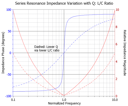
As mentioned previously, the \(Q\) can be a function of either \(R\) or the \(L/C\) ratio. In Figures \(\PageIndex{6}\) and \(\PageIndex{7}\) we have impedance curves for the two cases. The frequency axis is normalized to \(f_0\) (i.e., \(f_0\) is unity). In Figure \(\PageIndex{6}\) we vary the resistance value to see how it affects both the magnitude and phase of the impedance across frequency. Figure \(\PageIndex{7}\) is similar except we vary the inductor/capacitor ratio.
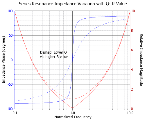
Looking first at the phase (blue, left axis), we see in both cases that high \(Q\) circuits exhibit a quick transition from a negative (capacitive) phase angle to a positive (inductive) phase angle. We also notice that the phase shift hits zero at \(f_0\), implying unity power factor.
The impedance magnitude plots show a slightly different story. While it is true that the higher \(Q\) plots are sharper, they get that way through different mechanisms. In the case of the resistor, a lower \(Q\) is achieved via a larger resistance. This has the effect of blunting the tip of the curve and lowering current flow at \(f_0\) when compared to the high \(Q\) case (as seen in Figure \(\PageIndex{3}\)). In contrast, reducing \(Q\) by reducing the inductor/capacitor ratio broadens the entire curve. The impedance magnitude at the dip does not change, and thus the current at \(f_0\) does not change. In practical terms, the \(Q\) for a series circuit, \(Q_{series}\), may also be defined by the ratio of circuit reactance to the total series resistance at resonance.
\[Q_{series} = \frac{X_0}{R_T} \label{8.12} \]
\(Q_{series}\) is the \(Q\) of the series resonant circuit (i.e., \(Q_{circuit}\) for series),
\(R_T\) is the total series resistance (\(R_{series} + R_{coil}\)),
\(X_0\) is the reactance (either \(X_L\) or \(X_C\)) at \(f_0\).
From Equation \ref{8.12} we can derive an expression for \(Q_{series}\) in terms of \(R\), \(L\) and \(C\) as follows:
\[Q_{series} = \frac{X_0}{R_T} \nonumber \]
\[Q_{series} = \frac{\sqrt{X_0^2}}{R_T} \nonumber \]
At resonance \(X_L\) and \(X_C\) have the same magnitude, thus we can also say:
\[Q_{series} = \frac{\sqrt{X_L X_C}}{R_T} \nonumber \]
\[Q_{series} = \frac{1}{R_T} \sqrt{X_L X_C} \nonumber \]
\[Q_{series} = \frac{1}{R_T} \sqrt{ \frac{2 \pi f L}{2\pi f C}} \nonumber \]
Which simplifies to:
\[Q_{series} = \frac{1}{R_T} \sqrt{\frac{L}{C}} \label{8.13} \]
Effect of Q on Component Voltages
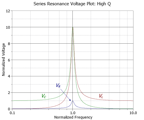
\(Q\) will create a multiplying effect on the inductor and capacitor voltages at resonance. At \(f_0\), the current through the circuit will equal the source voltage divided by \(R\) because \(X_C\) and \(X_L\) cancel. This current is also flowing through the capacitor and inductor. Equation \ref{8.12} shows that their reactances are \(Q\) times higher than \(R\), and therefore their voltages will be \(Q\) times higher than the source voltage. KVL is not violated because the voltages across \(L\) and \(C\) are 180 degrees out of phase and cancel each other. As the circuit \(Q\) is increased, the voltage multiplying effect becomes more pronounced. In extreme cases it is possible to produce inductor and capacitor voltages that are more than 100 times larger than the source voltage. As we move away from the resonant frequency, the multiplying effect decreases. At frequencies much lower than \(f_0\), almost all of the source voltage will appear across the capacitor with little for the resistor and inductor. At much higher frequencies, nearly all of the source potential appears across the inductor with nothing seen across the capacitor or resistor. This can be seen in Figure \(\PageIndex{8}\), where the source voltage is unity.
As \(Q\) decreases, not only do the capacitor and inductor voltages decrease, but another effect comes into play. At relatively high \(Q\) values, say 10 or more, the capacitor and inductor maximum voltages occur at approximately \(f_0\). At lower \(Q\) values the peaks tend to spread apart, with the capacitor's peak below \(f_0\) and that of the inductor above \(f_0\). This is illustrated in Figure \(\PageIndex{9}\) (again, the source is unity).
Example \(\PageIndex{1}\)
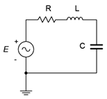
Consider the series circuit of Figure \(\PageIndex{10}\) with the following parameters: the source is 10 volts peak, \(L\) = 1 mH, \(C\) = 1 nF and \(R = 50 \Omega \). Find the resonant frequency, the system \(Q\) and bandwidth, and the half-power frequencies \(f_1\) and \(f_2\).
We begin by finding the resonant frequency.
\[f_0 = \frac{1}{2\pi \sqrt{LC}} \nonumber \]
\[f_0 = \frac{1}{2\pi \sqrt{1e-3\cdot 1e-9}} \nonumber \]
\[f_0 = 159 kHz \nonumber \]
We now find the magnitude of the inductive reactance, and from that, the system \(Q_{series}\) via Equation \ref{8.12}.
\[X_L = 2\pi f_0 L \nonumber \]
\[X_L = 2\pi 159 kHz 1mH \nonumber \]
\[X_L = 1000\Omega \nonumber \]
\[Q_{series} = \frac{X_L}{R_T} \nonumber \]
\[Q_{series} = \frac{1000\Omega}{50\Omega} \nonumber \]
\[Q_{series} = 20 \nonumber \]
Knowing the \(Q\), the bandwidth and corner frequencies can be found via Equations \ref{8.4}, \ref{8.10} and \ref{8.11}.
\[BW = \frac{f_0}{Q} \nonumber \]
\[BW = \frac{159 kHz}{20} \nonumber \]
\[BW = 7.95 kHz \nonumber \]
\[f_1 = f_0 − \frac{BW}{2} \nonumber \]
\[f_1 = 159 kHz − \frac{7.95kHz}{2} \nonumber \]
\[f_1 \approx 155 kHz \nonumber \]
\[f_2 = f_0 + \frac{BW}{2} \nonumber \]
\[f_2 = 159 kHz + \frac{7.95kHz}{2} \nonumber \]
\[f_2 \approx 163 kHz \nonumber \]
Given the 10 volt peak source, the voltages across the capacitor and inductor at the resonance frequency of 159 kHz would be \(Q\) times greater, or 200 volts. At higher or lower frequencies, the increased impedance lowers the current and also lowers the voltages across the components. At low frequencies, most of the source will appear across the capacitor while at high frequencies the inductor voltage will approach the source voltage.
Refining Series Q
As noted in Chapter 2, all inductors have some series resistance associated with them, usually called \(R_{coil}\). This resistance needs to be included as part of the overall circuit resistance, adding to whatever other series resistance exists. While it is possible to measure the DC resistance of a coil using a DMM, this will not necessarily give an accurate value at high frequencies. Thus, a preferred method is to determine \(Q_{coil}\) at the desired frequency from the inductor's spec sheet, and using the calculated reactance at that frequency, determine the value of \(R_{coil}\). An example of such a curve is shown in Figure \(\PageIndex{11}\).
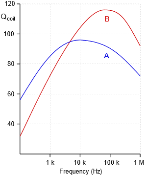
For instance, using curve A, \(Q_{coil}\) at 100 kHz is approximately 90. If \(X_L\) is 450 \(\Omega \) at this frequency, then \(R_{coil}\) would be 450 \(\Omega /90\), or 5 \(\Omega \).
Effectively, \(Q_{coil}\) sets the ceiling for the \(Q\) of the series resonant circuit, \(Q_{series}\). That is, the system \(Q\) can never be higher than the coil \(Q\). To do so would require less resistance in the loop than \(R_{coil}\), which is a practical impossibility. It is also worth noting that \(R_{coil}\) will create a deviation in the inductor voltage compared to the ideal case. This is because \(v_L\) covers the combination of the inductive reactance in series with \(R_{coil}\), thus the magnitude will be somewhat larger than expected and the angle will be less than 90 degrees. These deviations tend to be quite small unless the inductor's \(Q\) is fairly low and the remaining circuit resistance is not very much larger than \(R_{coil}\).
Example \(\PageIndex{2}\)
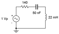
For the circuit of Figure \(\PageIndex{11}\), determine the resonant frequency, the system \(Q\), the bandwidth, and the ideal maximum voltage across each of the three components. Use curve A from Figure \(\PageIndex{11}\) for the inductor.
The first item of importance is finding the resonant frequency.
\[f_0 = \frac{1}{2 \pi \sqrt{LC}} \nonumber \]
\[f_0 = \frac{1}{2\pi \sqrt{22e-3 H50e-9F}} \nonumber \]
\[f_0 = 4.8 kHz \nonumber \]
The inductive reactance is:
\[X_L = 2\pi 4.8kHz 22 mH \nonumber \]
\[X_L = 663.3\Omega \nonumber \]
From the graph, \(Q_{coil}\) is approximately 95, meaning \(R_{coil}\) is:
\[R_{coil} = \frac{X_L}{Q_{coil}} \nonumber \]
\[R_{coil} = \frac{663.3 \Omega}{95} \nonumber \]
\[R_{coil} = 7\Omega \nonumber \]
Combined with the 140 \(\Omega \) resistor, we are left with 147 \(\Omega \), some 5% higher than if we had ignored it. The system \(Q\) is:
\[Q_{series} = \frac{663.3\Omega}{147\Omega} \nonumber \]
\[Q_{series} = 4.51 \nonumber \]
The \(Q\) is on the low side but not extremely so. Now for the bandwidth:
\[BW = \frac{4.8 kHz}{4.51} \nonumber \]
\[BW = 1.06 kHz \nonumber \]
Ideally, at \(f_0\) we expect \(v_R\) will be equal to the source of 1 volt peak while the inductor and capacitor voltages will be \(Q\) times larger, or approximately 4.5 volts peak. In reality \(R_{coil}\) will create a voltage divider, reducing the drop across the 140 \(\Omega \) resistor to about 0.95 volts. The change in \(v_L\) will be negligible due to \(Z_L\) being \(663.34\angle 89.4^{\circ} \Omega \) versus the ideal \(663.3\angle 90^{\circ} \Omega \). The system \(Q\) is relatively low (\(<10\)), so the \(v_C\) and \(v_L\) peaks will shift a little from \(f_0\), with \(v_C\) peaking at a slightly lower frequency and \(v_L\) slightly higher.
Computer Simulation
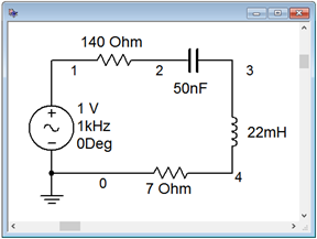
Of particular interest in the prior example is the precise shape of the component responses versus frequency. This can be produced via an AC or frequency domain simulation. The circuit of Figure \(\PageIndex{12}\) is captured in a simulator as shown in Figure \(\PageIndex{13}\), and is modified by adding the inductor's coil resistance below the inductor.
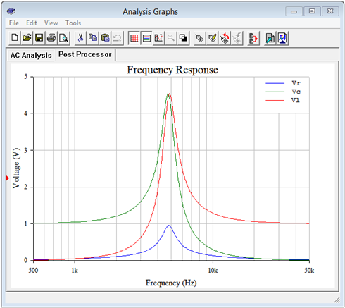
The items of interest are the net resistor voltage which appears between nodes 1 and 2, the capacitor voltage between nodes 2 and 3, and the inductor voltage which appears from node 3 to ground. The analysis is run from 500 Hz to 50 kHz giving us a factor of 10 in frequency on either side of \(f_0\), as seen in Figure \(\PageIndex{14}\). First, the peaks are just below 5 kHz, as expected. The resistor voltage (blue) is about 0.95 volts, and the inductor (red) and capacitor (green) voltages are about 4.5 volts, as calculated.
Also, note that there is a slight spread between the peaks of the capacitor and inductor voltages, with \(v_C\) slightly below \(f_0\) and \(v_L\) slightly above, again just as expected. At the lowest frequencies, all of the source appears across the capacitor while at the highest frequencies all of the source appears across the inductor. Note the similarity between these curves and those of Figures \(\PageIndex{8}\) and \(\PageIndex{9}\)
And now for a change of pace; a design problem.
Example \(\PageIndex{3}\)
Design a series resonant circuit with a resonant frequency of 100 kHz and a bandwidth of 2 kHz using a 10 mH inductor. Assumes the inductor follows curve B in Figure \(\PageIndex{14}\).
We can find the value for the capacitance by rearranging the resonance frequency equation:
\[\sqrt{LC} = \frac{1}{2\pi f_0} \nonumber \]
\[C = \frac{1}{(2\pi f_0 )^2 L} \nonumber \]
\[C = \frac{1}{(2\pi 100 kHz )^2 10mH} \nonumber \]
\[C = 253.3 pF \nonumber \]
Knowing the bandwidth and resonant frequency, we can find the system \(Q\):
\[Q_{series} = \frac{f_0}{BW} \nonumber \]
\[Q_{series} = \frac{100 kHz}{2 kHz} \nonumber \]
\[Q_{series} = 50 \nonumber \]
At resonance, the inductive reactance will be:
\[X_L = 2\pi 100 kHz 10 mH \nonumber \]
\[X_L = 6283\Omega \nonumber \]
The preceding tells us that the total series resistance must be:
\[R_{series} = \frac{X_L}{Q_{series}} \nonumber \]
\[R_{series} = \frac{6283\Omega}{50} \nonumber \]
\[R_{series} = 125.7\Omega \nonumber \]
Curve B indicates that \(Q_{coil}\) is approximately 115 at 100 kHz. Thus, \(R_{coil}\) is:
\[R_{coil} = \frac{6283\Omega}{115} \nonumber \]
\[R_{coil} = 54.6\Omega \nonumber \]
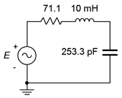
Consequently, we must add \(125.7 \Omega − 54.6 \Omega \), or \(71.1 \Omega \), to the series network to achieve the desired system \(Q\). Failure to do so will yield a much higher \(Q\) than specified, resulting in a much reduced bandwidth. The completed design is shown in Figure \(\PageIndex{15}\).
1 Decibels are covered in detail in Chapter 10.
Resonance in Series and Parallel RLC Circuit | Resonance Frequency
This article examines the resonance phenomenon and resonance frequency in series and parallel rlc circuits, along with several examples. .
In any AC circuit consisting of resistors, capacitors, and inductors, either in series or in parallel, a condition can happen in which the reactive power of the capacitors and of the inductors become equal. This condition is called resonance .
Simultaneous with the capacitive reactive power and the inductive reactive power being equal, other features can reflect resonance. Remember that we always reduce a circuit to a single resistor, a capacitor, and an inductor. Thus, for this discussion, we assume one of each component in the circuit.
Resonance: a Special condition in AC circuits where all the energy stored by inductive components is provided by capacitive components, and vice versa. This occurs in a particular frequency. This condition implies other facts such as:
- The net reactive power to be zero,
- The power factor to be unity, and
In fact, when resonance happens, the inductive reactance and the capacitive reactance are equal to each other:
$\begin{matrix} {{X}_{L}}={{X}_{C}} & {} & \left( 1 \right) \\\end{matrix}$

Figure 1. Resonance condition in Series and Parallel AC circuits.
In a circuit with a fixed frequency, resonance can happen if the condition in Equation 1 is true.
On the other hand, since both X L and X C are functions of frequency, if the frequency of a circuit changes, at a unique frequency these values can become equal.
Figure 1 shows the variation of the impedance for the three basic types of loads in a circuit versus frequency. The horizontal axis implies a frequency increase.
A resistor is independent of frequency; thus, its impedance is constant, represented by a line parallel to the horizontal axis. The impedance of an inductor is proportional to the frequency and augments as the frequency increases. For a capacitor the reverse happens and its impedance decreases (though not linearly) as the frequency increases.
At the point of intersection of the two curves, X L = X C, and the frequency at that point is called the resonant frequency or resonance frequency and is denoted by f R .
Resonant frequency: A unique frequency for each AC circuit containing both reactive components (inductors and capacitors) at which the resultant reactance of all capacitive components is equal to the resultant reactance of all the inductive components. As a result, the two types of components cancel the effect of each other, and the total reactive power of the circuit is zero.
Resonance frequency: Frequency at which resonance happens in an AC circuit.
The resonance frequency can be found by equating X L and X C . This leads to
\[\begin{matrix} {{f}_{R}}=\frac{1}{2\pi \sqrt{LC}} & {} & \left( 2 \right) \\\end{matrix}\]
Resonance Frequency Calculation Example 1
Find the resonance frequency of a 40 mH inductor and a 51 μF capacitor.
Values of the capacitance and inductance in Farad and Henry can directly be plugged in Equation 2 . Thus,
\[{{f}_{R}}=\frac{1}{2\pi \sqrt{LC}}=\frac{1}{2\pi \sqrt{0.040*0.00051}}=112Hz\]
Resonance Frequency Calculation Example 2
Find the capacitance for a capacitor to become in resonance with a 40 mH inductor at 60 Hz frequency.
At 60 Hz the reactance of the capacitor must be the same as the reactance of the inductor. Thus,
$\begin{align} & {{X}_{C}}={{X}_{L}}=2\pi *60*0.040=15\Omega \\ & C=\frac{1}{2\pi *60*15}=176mF \\\end{align}$
Note that if this value is not among the standard values for capacitors, one can make such a value by combining a number of standard capacitors in series and/or parallel.
Resonance in Series RLC Circuits
When resonance occurs in a series RLC circuit , the resonance condition ( Equation 1 ) leads to other relationships or properties. These are
- The voltage across the inductor is equal to the voltage across the capacitor.
- The voltage across the resistor is equal to the applied voltage.
- The impedance of the circuit has its lowest value and is equal to R .
- Circuit current assumes its maximum value because the impedance is minimum.
- The power factor for the circuit becomes equal to 1, and the phase angle is zero.
- Apparent power has its lowest value and becomes equal to the active power because the power factor is 1.
Resonance in Parallel RLC Circuits
Similar to the series circuits, when resonance occurs in a parallel RLC circuit the resonance condition ( Equation 1 ) leads to other relationships or properties:
- The current in the inductor is equal to the current in the capacitor.
- The current in the resistor is equal to the total circuit current.
- The impedance of the circuit has its highest value and is equal to R .
- Circuit current assumes its minimum value because the impedance has the highest value.
Items 5 and 6 are the same as for the series resonant circuits, but the rest are quite different.

Figure 2. Principle of induction heater and induction cooker.
When resonance occurs in a parallel RLC circuit, a local current circulates between the inductor and the capacitor. This current can be very high, while the circuit current as seen from the source can be low. This phenomenon is used in induction heaters (in the industry for heating metals when necessary, e.g., heating bearings for mounting or dismounting) and in induction cookers (for domestic use).
In such an application a high current is flowing through an inductor, whereas the current provided by the power line is small. This means that the rating of the wires and breakers is much smaller than the current in the inductor.
The current in the inductor creates (induces) local currents in the piece to be warmed, without even touching it. In the case of an induction cooker, the body of the cooking pan becomes hot owing to local currents created by induction. This is shown in Figure 2 .
The efficiency of induction heating is very high, and the process is very fast compared to conventional heating in which a great part of the energy is used for heating air and the intermediate media between the source and the body to be heated.

LAB 8: RESONANCE CIRCUITS
Demonstrating resonance phenomena in RLC circuits. Measurements of resonance characteristics and their comparison with theory.
INTRODUCTION
Resonance is one of the most important and general phenomenon in almost all branches of science and technology. For example, in mechanical systems a resonance is often seen in vibrations of a beam or a spring supporting a mass. Vibrations are caused by transfer of the potential energy stored by the beam deflection or the spring contraction to the kinetic energy of the moving mass, back and forth in a periodic motion. In electrical circuits the energy stored in the form of the electric field in a capacitor is transferred to the electric current in the circuit in which inductance plays a role equivalent to the inertial mass in a mechanical system. The equations describing both resonances are identical, only their coefficients have values related to mechanical (mass, spring constant) or electrical (capacitance, inductance) parameters. Another important analogy between the two systems is that the vibrations can be damped; by friction in mechanical systems and by resistance in electrical circuits.
The resonance can be very useful in such devices as oscillators in radio transmitters or electronic watches. More often, however, they can be harmful by generating unwanted wide deflections of mechanical systems (bridges, airplane wings, etc.) or oscillations of voltage and current. Controlling or preventing unwanted resonance is an important aspect of engineering design. Since every electrical component, or even a connecting wire, has some capacitance and inductance there is a potential for resonance in every circuit. As you already know, the smaller the values of inductance and capacitance, the higher the resonance frequency. That is why design of high frequency circuits is so much more difficult as even small inductance and capacitance of connections plays a role. In this set of experiments you will explore resonance in a series RLC circuit, which have the resonance in relatively low and easy to handle frequency range.
| Important Relations in Electrical Resonance: |
Sketch the so called resonance curve for the series resonance circuit in Fig. 7. Put on the vertical axis the current (or voltage across resistor R) and log f on the horizontal axis. Indicate the resonance frequency f o and the width of the resonance curve (the bandwidth), which is the interval Δf = 2πΓ between two frequencies at which the power dissipated in the circuit is ½ of the maximum. Calculate these numbers for specific component values which you may use in the laboratory, for example: R = 1k, C = 1nF, L = 50 mH.
Hint: Note that the three components are connected in series with a voltage source, so it is easy to write an expression for the current (using complex numbers). The current reaches maximum (resonance) for a certain frequency at which the total circuit impedance is equal to R (what is the phase of the current at this frequency?). At half power frequencies the current drops to 1/√2.
Once you have the expression for current you may well use it in a spreadsheet program (such as MS Excel) or use some other software (such as Matlab) to calculate and plot the resonance curve (ratio V R /V s as a function of log f ). You will need it also for your report.
Alternatively, you may simulate the circuit operation with Multisim. Print the frequency response curve using a semi-log plot for the R, L and C components given above. For the lab report, modify the simulation with the actual values of the components used in the laboratory.
Independently of the method of generating the resonance curve (your own calculations or Multisim), determine the number of data points and their location (frequency) for best determination of the resonance frequency and the bandwidth.
Equipment needed from the stockroom: Proto-board, leads, scope probes.
1. SERIES RESONANCE CIRCUIT DRIVEN BY A SINUSOIDAL VOLTAGE
a) Assemble the series resonance circuit shown below. Use 50 mH coil from your parts kit for L, select a resistor about 1 k ohms and a capacitor of 1 to a few nF. Measure the values of these components before assembly. Measure also the coil resistance with the digital ohmmeter. Calculate the expected resonance frequency. Fig. 7 Series resonance circuit
b) Attach one scope probe across the voltage source, the other across R and observe the two signals on different scope channels simultaneously. Note amplitudes and phase difference while changing the frequency. If the voltage amplitude of the generator vary with frequency, you may adjust it to keep it constant, otherwise note its values for different frequencies. Obtain sufficient number of data points for plotting of the resonance curve. Try to determine precisely the resonance frequency at the peak of the curve and the frequencies at the half power points on both sides of the maximum. Measure also the phase shift between V s and V R at these three frequencies and a few other frequencies on both sides of the maximum. It is usually easier to find precisely the resonance frequency from the phase measurement than from the amplitude. c) Measure also the voltage across the capacitor at the resonance by using the signal subtraction function of the digital oscilloscope, which subtracts signals of the two scope channels. Note that it is larger than the generator voltage. The ratio of these voltages is equal to the Q value of the circuit.
2. RESONANCE CIRCUIT EXCITED WITH A STEP VOLTAGE
Switch the waveform generator from a sine wave to a square wave at the resonance frequency of the circuit. What is the shape of the current waveform? Can you explain this observation? Next, adjust the square wave frequency to about one tenth of the circuit resonance frequency. Expand the image horizontally and observe the signal shape after the step of the input signal. Print the scope image. Can you determine the frequency of the oscillations? The image shows a response of any resonance system to an external disturbance represented here by a pulse (square wave).
3. CIRCUIT SIMULATION (at home).
Simulate measurements 1 and 2: frequency response of amplitude and phase and the time dependence of current with a square wave input. Use the same values of R, L, and C in simulations as in the laboratory. Compare results of simulations with measurements.
- Make graphs of the resonance curves showing the amplitude (plot V R /V S ) and the phase ( ∠ V R − ∠ V S ). Put the calculated (simulated) results in the form of continuous curves and the experimental data as points on the same graph.
- Compare the measured values of the resonance frequency and the widths of the resonance curves at half power maximum (the bandwidth) with the values calculated or simulate for the circuits components actually used in the laboratory. How does the phase change across the resonance curve?
- Compare results of 1 c ) with calculated Q and the Γ obtained from the frequency distribution in 1 b ).

Resonance in Series RLC Circuit

Consider a series RLC circuit where a resistor , inductor and capacitor are connected in series across a voltage supply. This series RLC circuit resonates at a specific frequency known as the resonant frequency. In this circuit containing inductor and capacitor, the energy is stored in two different ways.
Variation in Inductive Reactance and Capacitive Reactance with Frequency
Variation of inductive reactance vs frequency, variation of capacitive reactance vs frequency.
The formula for capacitive reactance X C = 1 / 2πfC shows that frequency and capacitive reactance are inversely proportional. At zero frequency (DC), capacitive reactance is infinite, and the circuit acts as an open circuit. As frequency increases, capacitive reactance decreases and becomes zero at infinite frequency, making the circuit act as a short circuit. The graph of capacitive reactance versus frequency forms a hyperbolic curve.
Inductive Reactance and Capacitive Reactance Vs Frequency
Variation of impedance vs frequency, resonant current, power factor at resonance.
At resonance, the inductive reactance is equal to capacitive reactance and hence the voltage across inductor and capacitor cancel each other. The total impedance of circuit is resistance only. So, the circuit behaves like a pure resistive circuit and we know that in pure resistive circuit, voltage and the circuit current are in same phase i.e V r , V and I are in same phase direction. Therefore, the phase angle between voltage and current is zero and the power factor is unity.
Application of Series RLC Resonant Circuit
Leave a comment cancel reply.

COMMENTS
In complex form, the resonant frequency is the frequency at which the total impedance of a series RLC circuit becomes purely "real", that is no imaginary impedance's exist. This is because at resonance they are cancelled out. So the total impedance of the series circuit becomes just the value of the resistance and therefore: Z = R.
The resonant frequency for a RLC circuit is calculated from Equation 15.6.5, which comes from a balance between the reactances of the capacitor and the inductor. Since the circuit is at resonance, the impedance is equal to the resistor. Then, the peak current is calculated by the voltage divided by the resistance. Solution.
frequency, the current in the circuit is also a maximum, since V R = IR. Thus, from Equations 6 and 7, this is the resonant frequency of the RLC circuit. 13. Now change the display setting so that you again see both V R from CH1, and V RLC from CH2. From Equations 8 and 9, the reactance from the inductor (X L = !L) and the reactance from the ...
Exp. E11: RLC Resonant Circuit 11 -6 E. Frequency response of resonant RLC circuit Here will find the voltage across the resistor, VR, as a function of frequency, for the RLC circuit shown in Figure 11-2. In the experiment will plot these quantities, and you will find a resonance, as shown in Figure 11-4. Using Eq. (11.5), we see that VR = I R ...
Figure 1: Parallel Resonance Circuit. Consider the Parallel RLC circuit of figure 1. The steady-state admittance offered by the circuit is: Y = 1/R + j( wC - 1/wL) Resonance occurs when the voltage and current at the input terminals are in phase. This corresponds to a purely real admittance, so that the necessary condition is given by.
Figure 23.3.2: This graph shows the relationships of the voltages in an RLC circuit to the current. The voltages across the circuit elements add to equal the voltage of the source, which is seen to be out of phase with the current. An RLC series circuit has a 40.0Ω resistor, a 3.00 mH inductor, and a 5.00μF capacitor.
Current, voltage, and impedance in an RLC circuit are related by an AC version of Ohm's law: I0 = V0 Z orIrms = Vrms Z. 23.63. Here I0 is the peak current, V0 the peak source voltage, and Z is the impedance of the circuit. The units of impedance are ohms, and its effect on the circuit is as you might expect: the greater the impedance, the ...
11. The Series RLC Resonance Circuit Introduction Thus far we have studied a circuit involving a (1) series resistor R and capacitor C circuit as well as a (2) series resistor R and inductor L circuit. In both cases, it was simpler for the actual experiment to replace the battery and switch with a signal generator producing a square wave.
Part 2: Energy Ringdown in an Undriven RLC Circuit Part 1 is repeated, except that the energy is reported instead of current and voltage. Part 3: Driving the RLC Circuit on Resonance Now the circuit is driven with a sinusoidal voltage and you will adjust to frequency while monitoring plots of I(t) and V(t) as well as V vs. I.
Series Resonance. The resonance of a series RLC circuit occurs when the inductive and capacitive reactances are equal in magnitude but cancel each other because they are 180 degrees apart in phase.The sharp minimum in impedance which occurs is useful in tuning applications. The sharpness of the minimum depends on the value of R and is characterized by the "Q" of the circuit.
The impedance of an RLC series circuit at resonance is simply R. Figure 9-1 Series RLC circuit . Series-Parallel Resonance Parallel resonance is more difficult to define due to the fact that in real life the inductor will have a resistive value. There are three methods for defining parallel resonance, each resulting in a different resonant ...
Figure 8.2.9: Series resonance: component voltages for low Q. Example 8.2.1. Consider the series circuit of Figure 8.2.10 with the following parameters: the source is 10 volts peak, L = 1 mH, C = 1 nF and R = 50Ω. Find the resonant frequency, the system Q and bandwidth, and the half-power frequencies f1 and f2.
For a series RLC circuit, Q= ! 0L=R, which is the inductive reactance at resonance divided by the resistance. The Q of an oscillating system can be de ned as Q= 2ˇ the energy stored in the circuit the energy lost per cycle (6) 3.1 Q and the Undriven Series RLC Circuit If R is low enough and the series RLC circuit is excited and the left alone ...
The LC circuit. In the limit R →0 the RLC circuit reduces to the lossless LC circuit shown on Figure 3. S C L vc +-+ vL - Figure 3 The equation that describes the response of this circuit is 2 2 1 0 dvc vc dt LC + = (1.16) Assuming a solution of the form Aest the characteristic equation is s220 +ωο = (1.17) Where
The Series RLC Circuit and Resonance Purpose a. To study the behavior of a series RLC circuit in an AC current. b. To measure thevalues of the L and C using impedance method. c. To study the resonance behavior in a series RLC circuit. Theory In this lab exercise, you will use the same hidden RLC circuit that you worked with last
Resonance frequency: Frequency at which resonance happens in an AC circuit. The resonance frequency can be found by equating XL and XC. This leads to. f R = 1 2π√LC (2) f R = 1 2 π L C ( 2) Resonance Frequency Calculation Example 1. Find the resonance frequency of a 40 mH inductor and a 51 μF capacitor.
PRELAB. Sketch the so called resonance curve for the series resonance circuit in Fig. 7. Put on the vertical axis the current (or voltage across resistor R) and log f on the horizontal axis. Indicate the resonance frequency f o and the width of the resonance curve (the bandwidth), which is the interval Δf = 2πΓ between two frequencies at which the power dissipated in the circuit is ½ of ...
Experiment 4: Damped Oscillations and Resonance in RLC Circuits. An RLC circuit is a damped harmonically oscillating system, where the voltage across the capaci-tor is the oscillating quantity. In the first part of this lab, you will experiment with an underdamped RLC circuit and find the decay constant, β, and damped oscillation frequency ...
May 30, 2024 by Electrical4U. Contents. 💡. Key learnings: Resonance in Series RLC Circuit Definition: Resonance in a series RLC circuit is when the inductive reactance equals the capacitive reactance, causing maximum current flow. Inductive Reactance: Inductive reactance increases with frequency, behaving like an open circuit at high ...
the experiment. R E = _____ ( ) 2) Connect the voltage source, multimeter and 2 voltage sensors to the RLC module and Pasco interface as shown in Figure 4. 3) Create an appropriate experiment in DataStudio. Use a Sine Wave with a 5 V amplitude and a 4000 Hz frequency. 4) In order to find the resonant frequency manually, set the step
This video measures the voltage across the resistor in a series RLC circuit compared to the voltage across all three elements when an AC signal is applied ac...
Experiment 11: Driven RLC Circuit. 1. To measure the resonance frequency and the quality factor of a driven RLC circuit by creating a resonance (frequency response) curve. 2. To see the phase relationships between driving voltage and driven current in such a circuit at, below, and above the resonance frequency. 3.
A parallel circuit containing a resistance, R, an inductance, L and a capacitance, C will produce a parallel resonance (also called anti-resonance) circuit when the resultant current through the parallel combination is in phase with the supply voltage. At resonance there will be a large circulating current between the inductor and the capacitor due to the energy of the oscillations, then ...
The current at resonance in a series R-L-C circuit is 0.12mA. The circuit has an induc- tance of 0.05 H and the supply voltage is 24 mV at a frequency of 40 kHz. Determine (a) the circuit resistance and (b) the circuit capacitance.
A series resonant circuit is to be used to produce a high voltage at a frequency of 400 Hz. The inductor has an inductance of 15 mH and a wire resistance of 2 . How much capacitance should be connected in series with the inductor to produce a resonant circuit? The voltage supplied to the circuit is 240 V at 400 Hz.